Wednesday, December 13, 2017

Assembling the Chinese RTL-SDR Kit (Software Defined Radio)

I am building a Chinese RTL-SDR Kit.  To start with I was trained in soldering by MERP (Miniature Electronics Repair) school in the US Navy.  I was taught NASA standards for soldering.  They will surely disown me after seeing these pictures of my soldering. This kit is NOT easy!  I also work for a communications company.  I have built all kinds of communications equipment including surface mounted parts and hand wound coils.

Here is what the kit parts look like.  There are many really tiny parts in the parts bag!

The circuit board comes with none of the surface mount parts installed.

To solder the surface mounted parts you will need a magnifying headband visor.  You will also need tweezers and a really fine soldering tip. Apply a small amount of solder to one pad and place one end of the part in the molten solder.  Then solder the other end.  Then clean up the first side.  The surface mount parts are marked except for the 222 resistors, the LED and the 4.7uH choke.  The LED is in a black part holder and has a green stripe.  There are extras of some parts in case you loose some.


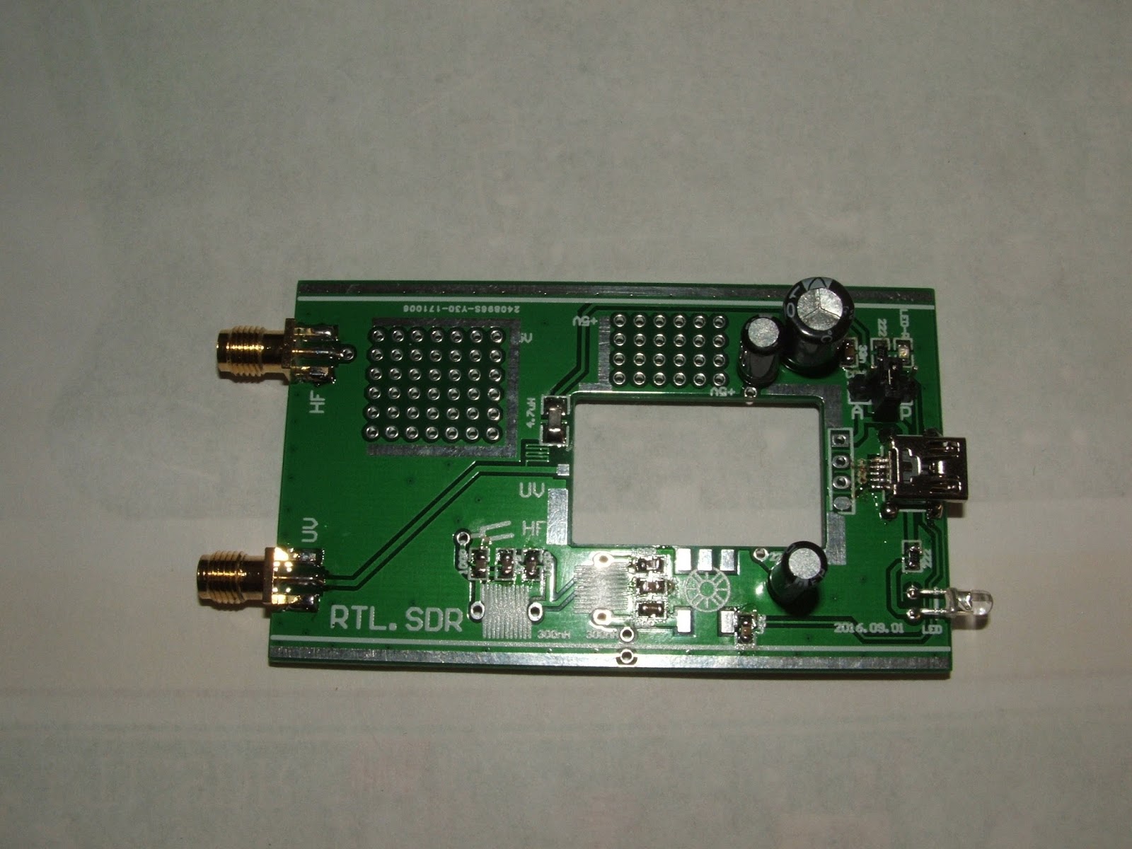
Here is a picture of the circuit board with the surface mounted parts jacks, and capacitors added.  The green stripe of the LED goes towards the USB jack.  The USB Jack is really hard to solder.  I ended up with a solder bridge.  After trying every trick to get rid of the bridge I resorted to using solder wick to soak up the extra solder.  The capacitors should have their ground stripes facing the outer edges of the board.

I skipped adding the coils and went right to the disassembling USB dongle.  Use solder wick to remove the solder on the ground connections.  Then clip off the four USB jack pins using flush cutters.  Then clear the metal out of the holes with a solder sucker. (Or heat and tap).

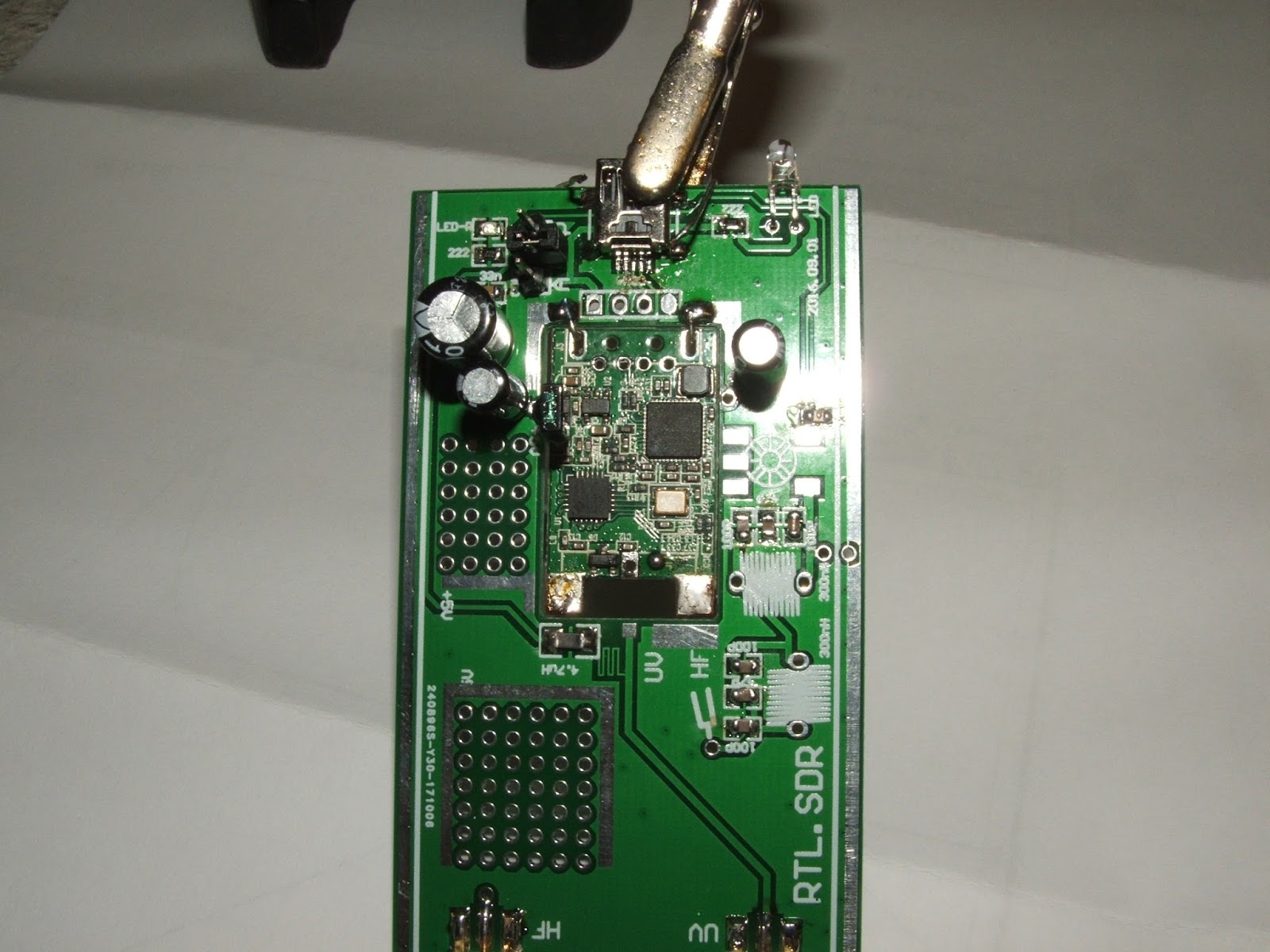
To add the USB assembly make two jumper hooks out of the former capacitor wires.  Use them to hold the USB assembly up as in the following picture.  Then solder them in place on both the top and bottom sides.

Next make a |_____| to connect the bottom grounds together as in the next picture.
Then add the four USB jumpers (from the old USB jack holes to the new jacks holes), two ground jumpers, and the RF input jumper on the top side of the board.

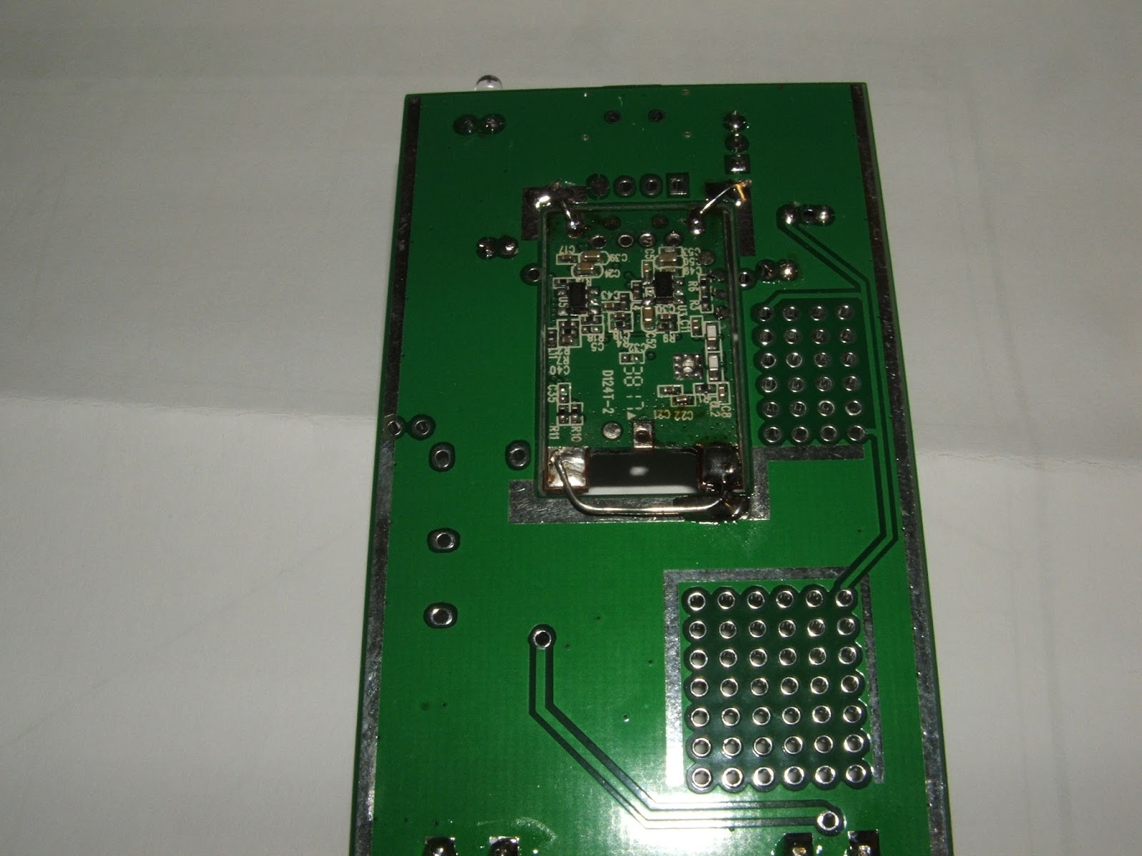
There is a jumper to add to the bottom of the board.  It runs from one of the pins of a five pin device (likely a voltage regulator) to the edge.

It is easiest to attach the jumper just to the lower side of one of the pins as seen in this next illustration.

Then there is also an extra jumper to run on the top side.  It also runs from one of the pins of a five pin device to the edge.  It runs underneath the IR receiver, unless you have removed the IR (Remote Control) receiver.

There are two small coils to wind.  The specs say 11 turns on a 3mm (.118") drill bit.  From other peoples pictures it looks like some people are using a .125 (1/8 inch) drill bit instead.

 Here it what it looks like with those coils installed.

Next is the beginning of the hardest part.  Making and installing the 25 MHz coil.  First the wire was all one color.  That will require a voltmeter to figure out.  Second it was one wire.  You will need three lengths of wire about one foot each.  You can mark the ends with colors with a permanent marker if you do not have a meter.  Twist the three wires together to form one three conductor wire.  You might need a needle to thread it through the ferrite bead 9 times.


Next label and meter the wires.  You will have to tin them first to get through the enamel.

Twist the Y* and R wires together and solder it to the circuit board. You should have Y then Y*R then R*. Then cut off the B leads and the two that are twisted together.


Monday, December 4, 2017

SainSmart DDS120/DDS140 USB DSO Oscilloscope

I just purchased a SainSmart DDS140 DSO on eBay. So far I have figured out how to get a trace on the screen using the built in signal generator.  Who puts the "Start" button in the bottom right corner?  Next is to test it in some real world situations like my WS2812 LED strip signs.


This is the built in 1 KHz test signal.


This is the "0" bit for my WS2812 signs.  It is .19 us, it is supposed to be about .400 us.

This is the "1" bit for my WS2812 signs.  It is .57 us, it is supposed to be about .800 us.  I had to measure from the center line as the trigger had issues with the lower signal level.  In fact I had to write a version of the sign software that sent all 1's to be able to capture the pulses.


Monday, November 27, 2017

Big Audio Spectrum Analyzer with Arduino UNO+MSGEQ7+WS2812 LED Strips

I have finally been able to get the combination of a MSGEQ7 and WS2812 LED strips to work together.  The trick was to not use any machine language code.  Instead, to access the WS2812 I just used parallel output commands like this:
  PORTD= 0xFF;  // turn on
  PORTD= 0xFF;  // delay
  PORTD= 0xFF;  // delay
  PORTD= 0xFF;  // delay (add more for faster processors)
  PORTD= bits;  // send data
  PORTD= bits;  // delay
  PORTD= bits;  // delay
  PORTD= bits;  // delay
  PORTD= 0x00;  // Turn off;
Sending the same command over and over just results in a delay.

This setup gives 90 steps to the top.  I am missing one LED strip for the needed total of 14.  I will add three more strips as soon as they arrive from China.

Here are some links to the videos on YouTube.  For some reason they don't embed the videos like they used to?  I think they are working now.


This is the code for the right channel only, but blogspot might remove all of the < and > from the code.....

// BOB Davis Enhanced Version for sending data to 8 Parallel WS2812 strings
// Removed Assembler and simplified the code
// Changed to VU meter with MSGEQ7

// PORTD is Digital Pins 0-7 on the Uno change for other boards.
#define PIXEL_PORT  PORTD  // Port of the pin the pixels are connected to
#define PIXEL_DDR   DDRD   // Port of the pin the pixels are connected to

// MSGEQ7 pins
#define PIN_STROBE 9
#define PIN_RESET 10
#define PIN_LEFT 4 //analog input
#define PIN_RIGHT 5 //analog input

//band arrays
int left[7];
int right[7];
int col=0;

void readMSGEQ7() { //reset the chip
  digitalWrite(PIN_RESET, HIGH);
  digitalWrite(PIN_RESET, LOW);
  for(int band=0; band < 7; band++) {  //loop thru all 7 bands
    digitalWrite(PIN_STROBE,LOW);      // go to the next band
    delayMicroseconds(30);             // gather data
    left[band] = analogRead(PIN_LEFT); // store left band reading
    right[band] = analogRead(PIN_RIGHT); // store right band reading
    digitalWrite(PIN_STROBE,HIGH);     // reset the strobe pin
  }
}

// Actually send the next set of 8 WS2812B encoded bits to the 8 pins.
// The delay timing is for an Arduino UNO.
void sendBitX8( uint8_t bits ) {
  PORTD= 0xFF;  // turn on
  PORTD= 0xFF;  // delay
  PORTD= 0xFF;  // delay
  PORTD= 0xFF;  // delay (Add more for faster processors)
  PORTD= bits;  // send data
  PORTD= bits;  // delay
  PORTD= bits;  // delay
  PORTD= bits;  // delay
  PORTD= bits;  // delay
  PORTD= 0x00;  // Turn off;
}

// Set default color for letters
int red=1;
int green=1;
int blue=1;

void sendPixelRow( uint8_t row ) {
  // Send the bit 8 times down every row, each pixel is 8 bits each for R,G,B
    for (int bit=0; bit <8; bit++){     
      if (green==1)sendBitX8( row );
      else sendBitX8( 0x00 ); }
    for (int bit=0; bit <8; bit++){     
      if (red==1)sendBitX8( row );
      else sendBitX8( 0x00 ); }
    for (int bit=0; bit <8; bit++){     
      if (blue==1)sendBitX8( row );
      else sendBitX8( 0x00 ); }
 }
void setup() {
  PIXEL_DDR = 0xff;    // Set all row pins to output
  pinMode(PIN_RESET, OUTPUT); // reset
  pinMode(PIN_STROBE, OUTPUT); // strobe
}
void loop() {
  red=0;
  green=1;
  blue=0;
    readMSGEQ7();                   // collect samples
    cli();                          // No time for interruptions!
    for (int b=1; b > 90; b++){
      if (b > 60) {red=1; green=0;}
      else       {red=0; green=1;}
      col=0;
      if (right[0]-64 >= b) col=col+1;  // Send bytes as VU meter data
      if (right[1]-64 >= b) col=col+2;  // Send bytes as VU meter data
      if (right[2]-64 >= b) col=col+4;  // Send bytes as VU meter data
      if (right[3]-64 >= b) col=col+8;  // Send bytes as VU meter data
      if (right[4]-64 >= b) col=col+16;  // Send bytes as VU meter data
      if (right[5]-64 >= b) col=col+32;  // Send bytes as VU meter data
      if (right[6]-64 >= b) col=col+64;  // Send bytes as VU meter data
      sendPixelRow(col);
      }
    sei();                        // interrupts back on
    delay (50);
//  }
}


Thursday, October 26, 2017

Better to sell using Auctions instead of fixed price on eBay!

A while back eBay offered me a deal on fixed price 30 day listings, they were free.  I always look at the "buy it now" prices because I do not want to wait for an auction.  On top of that auction listings are 30 cents each so it made sense to switch, right?  Wrong!  My sales tanked.  So I have gone back to auctions.  First here is a picture of my 30 day listings after 15 or more days with typically 10-20 views over that time.

Now compare that to some auctions that are only 1 day old with 60-150 views per 24 hours!
So forget about the 30 day fixed price listings they are free but a total waste of time!

Tuesday, October 17, 2017

More problems and another solution to the Head Gasket Problem with Bar's Leaks Professional.

UPDATE - 3 months later and still no problems.  There has been little if any loss of Antifreeze nor any overheating of the motor.
UPDATE - 1 year later, I have added about one quart of antifreeze over the past year.  However the car is running on the hot side around 207 degrees.  There is no sign of foam in the oil or the antifreeze.  I started adding antifreeze every few weeks.
UPDATE - After 14 months it is going through a quart of antifreeze every two weeks.  There is some foam on the antifreeze filling cap.  I added the other 1/2 of the can of the gasket repair solution.

UPDATE - FOUR YEARS LATER it is still running, it takes about a quart of antifreeze a year.

My HHR overheated again only two months after the last time that I tried to fix it.  The radiator was down about two quarts of fluid.  This time I decided to spend some more money and get something that stays in the radiator.  It is called "Bar's Leaks Professional HEAD SEAL Blown Head Gasket Repair" and runs about $45.  Just add 1/2 the container to the antifreeze - for a 4 cylinder engine.

Bar's Head Gasket Repair

Its only been a few days but so far so good.  I might have to change the oil once again. It looks a little brown.  There was no foam on the oil fill cap this time.

Sunday, October 15, 2017

What my Lab/Office looks like

I thought I would update what my office looks like.  Maybe I am bored or lacking in posts this year so I thought I would post something.  My F-550 is hanging from the ceiling with only its legs visible.  I am now using a rolling desk for my 3D printer 24 inch monitor and tools.  There is another book shelf to the right but it has not changed any.  My CNC found itself hidden in the closet....
I have a "New to me" notebook computer.  Its a EliteBook 8560W.  It was $5 at a Hamfest because of a bad screen.  The necessary repairs are elsewhere on my blog.

Saturday, September 9, 2017

Lancaster NY 2017 Hamfest

I think this was my first time at the Lancaster NY Hamfest.  It was also the first time I used my latest LED sign.  I had to misspell Arduino as I had a 6 character limit.  Here are some pictures of my stuff for sale.  The sign is running off a car battery with a 5 volt 10 amp regulator module.


Here are some pictures of interesting items for sale.


Friday, August 4, 2017

E470i LED Back-lit TV Repair

I picked up a 47 inch LCD TV with LED back-light that was no longer working.  I discovered that these LED back-lit TVs have the LED's wired in series and that eventually one opens up and the lights go out.

To dissemble the TV start by removing the back cover.  Then remove the metal cover in the foreground of the next picture it covers the LCD Connectors.

The cables need to be un-taped before they can be disconnected.  There is a black lock that flips out to release the cables.
Then remove the front bezel.  Besides lots of screws on all four sides there are some tabs across the bottom as can be seen in the front center of this picture.


Then there are several catches that will need to be unhooked.

The screen lifts out, being careful about the ribbon cables that are still connected to it.  Then there are four metal strips that hold the back-light filters in place.  There is a solid plastic filter and three flexible filters that will fall out if you are not careful.  Be careful to keep them in the right order but set them somewhere out of the way.
 Next is to remove the last layer covering the LED strips.  You will need to remove the pins that hold the plastic back and control the spacing to the front.  Two of them are under the power supply board.
 They are removed by pinching them with needle nose pliers on the back side.

Now to remove and test the LED strips.  They can be carefully pealed up with a flat blade screwdriver.  I used my fingernails to get underneath them to start the process.  Each strip has 4 or 5 three volt LED's (12 to 15 volts).  You can use two old 9 volt batteries to test them.  There should be a 100 ohm resistor in series with the batteries.  The end strips are tested by applying power to the test points near the connector.  The middle strips are tested the same way but you will need to short out the opposite end connector.

You will likely find 2 dead strips and maybe some dead LED's as well.  I actually broke one LED strip in the process of removing it.
Once you have the LED strips replacements you can test them out by removing the power distribution bad and testing them out like in the following picture before reassembling everything.  Remember that there are two sets of LED strips.

Here is a video on testing LED strops with 9 volt batteries:

HHR Head Gasket Repair

Update - After two months the car lost 2 quarts of antifreeze so I am trying another solution.  To be honest I did not follow the K&W directions completely.  Like you cannot leave the thermostat out of an HHR or it will leak badly.  See https://bobdavis321.blogspot.com/2017/10/more-problems-and-another-solution-to.html

My HHR overheated at a red light.  With the heat on I was able to get the temperature down to 235 degrees.  I added a gallon of water but two days later it needed more water.  Then I noticed that it was leaving puddles of water in the driveway under the exhaust pipe and spraying water 2 feet out from the tail pipe.  Then I saw the water bubbling in the radiator cap.  Is that absolute proof that the head gasket is blown?  After some praying and searching I used K&W Head Gasket Repair and now it is running fine again.

The directions require that you drain the radiator first and fill it with water.  Finding he drain in the HHR is next to impossible.  You cannot see it from above or below.  If you pull back the radiator plastic cover on the left side you might see one white plastic ear.  It is barely reachable but it can be removed.  

This video shows the bubbling.

The thermostat is also next to impossible to reach.  You will need a 10 mm socket and several extensions to get to the bolts.  You cannot leave the thermostat out as it will leak.  The seal is part of the thermostat.  But opening it up makes it easier to flush the cooling system.


After running the car for a while you once again drain everything and refill the cooling system. I did not think it was fixed because it was still running over 210 degrees.  However the radiator cap now had a seal when you try to open it.  Over the next few days of running the temperature slowly came back down to normal 196 degrees.

These cars run hotter than normal because the thermostat is on the return line from the radiator.  If the radiator offers 16 degrees of cooling then a 180 degree thermostat will allow the water to run at 196 degrees.  It gets even hotter while sitting still because the radiator fan does not come on until it reaches about 220 degrees.

Wednesday, August 2, 2017

FlameWheel F-450 with KK5.5 Controller one ESC went up in smoke!

I was flying my F-450 this time with a KK5.5 Flight Controller and one of the ESC's went up in smoke.  This is what the guts of the ESC looked like afterwards.

Here is the video.  I am still learning how to fly this thing.  It takes lots of practice (and crashes).

Monday, July 31, 2017

My New To Me Huskee LT-3800 Mower

I picked up a three year old Huskee LT-3800 Mower for $220.  The seller thought it was dead but I was able to start it, so I bought it.
The first thing I had to to fix was the cable for engaging the blades.  It is a 55" cable found on eBay for about $12.  The replacement cable works great.
The next problem was that it would quit after one lap around the yard and would not restart for several minutes.  There was a clog in the intake to the carburetor.  I completely rebuilt the carburetor but all that needed to be done was to remove the clog with a jewelers screwdriver and then clean it up with a pipe cleaner.  The red arrow shows where the problem was.

Tuesday, July 25, 2017

2017 Batavia Hamfest

I forgot to take my camera to the Batavia Hamfest.  My cellphone took some poor quality pictures.

Here is a picture of my stuff.  It was kind of rainy so I had to move it back under the rear hatch later on.

Here are some of the other vendors.  As you can see it was a little muddy.
I only took one picture of a unique piece of electronics.  This is an antenna tuner.


My laptop computer died again

Sunday evening my laptop computer died again.  It was one of those HP laptops with the graphics chip that has to be resoldered with a heat gun.  This time it only lasted for a year. See: http://bobdavis321.blogspot.com/2016/08/hp-pavilion-dv9000-series-resolder-or.html

However at the Batavia Hamfest I picked up a really nice quad core laptop for $5 that needed a hard drive and a screen.  I ordered the replacement screen on eBay but the post office has sent it all over the place.
Out of desperation I hooked up a screen from a laptop that had been replaced a while back because it has a black "hole" on it.  I was amazed that a total mismatch worked!  Now to add some duct tape to hold it in place until the correct screen arrives.
The problem with the non working screen is that the LED back-light connector is burnt up.  I do not know how common that problem is or if it can be jury rigged somehow?

Here is a better picture of the fried LED back light jack with its cover removed.

I soldered wires to the cable and the LED strip still did not work so I opened it up and it is toast.  I think it overheated, perhaps like the LED back lit TV's the LED's are being pushed to the point that they short out and "China Syndrome".
The problem with the overheated LED backlight went all the way through to the motherboard!